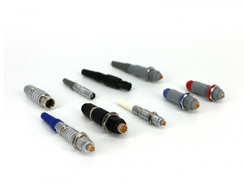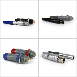
There are many types of electronic connectors, but the manufacturing process is basically the same. The manufacture of connectors can be generally divided into four stages: stamping, electroplating, injection molding and assembly.
1, stamping
The manufacturing process of the electronic connector generally begins with a stamped pin. Through large high-speed presses, the electronic connectors (pins) are stamped from thin metal strips. One end of the large-volume metal strip is fed into the front end of the punching machine, and the other end is wound into the take-up reel through the hydraulic working table of the punching machine, and the metal strip is pulled out by the take-up reel and rolled out to punch out the finished product.
2, plating
After the connector pin is stamped, it should be sent to the plating section. At this stage, the connector’s electronic contact surface will be plated with various metal coatings. A type of problem similar to the stamping phase, such as twisting, chipping or deformation of the pins, also occurs during the process of feeding the punched pins into the plating equipment. Through the techniques described in this article, such quality defects are easily detected. However, for most machine vision system suppliers, many of the quality defects that occur during the plating process are also the “forbidden zone” of the inspection system. Electronic connector manufacturers want the inspection system to detect various inconsistencies such as small scratches and pinholes on the connector pin plating surface. Although these defects are easily identifiable for other products, such as aluminum can bottom covers or other relatively flat surfaces, visual inspection systems are difficult to obtain due to the irregular and angular surface design of most electronic connectors. It is enough to identify the images needed for these subtle defects. Since some types of pins need to be coated with multiple layers of metal, manufacturers also want the inspection system to be able to distinguish various metal coatings to verify that they are in place and in the correct proportions. This is a very difficult task for a vision system using a black and white camera, since the gray levels of the images of different metal coatings are practically similar. Although the color vision system’s camera can successfully distinguish these different metal coatings, the problem of illumination difficulties still exists due to the irregular angle and reflection of the coating surface.
3, injection molding
The plastic case of the electronic connector is made during the injection molding stage. The usual process is to inject molten plastic into a metal film and then rapidly cool it. The so-called “leakage” occurs when the molten plastic fails to completely fill the membrane. This is a typical defect that needs to be detected during the injection molding stage. Other drawbacks include filling or partial blockage of the jacks (the jacks must be kept clean and unobstructed for proper insertion with the pins during final assembly). The machine vision system for quality inspection after injection molding is relatively simple and easy because the backlight can be used to easily identify the missing box and the plug.
4, assembly
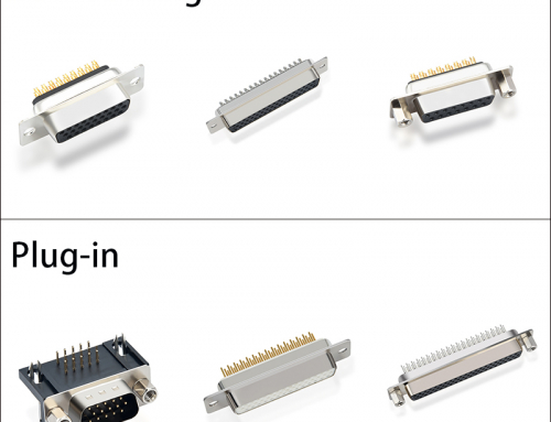
The final stage in the manufacture of electronic connectors is the assembly of finished products. There are two ways to insert the plated pins into the injection box holder: single or combination. Separate plug-in means that each pin is plugged in; each time the plug-in is inserted, the pins are plugged into the box at the same time. Regardless of the type of plug-in, the manufacturer requires that all pins be tested for missing and properly positioned during the assembly phase; another type of routine inspection task is related to the measurement of the spacing on the mating surface of the connector. As with the stamping phase, the assembly of the connector also presents a challenge in the detection speed for the automatic inspection system. Although most assembly line beats are one to two per second, for each connector that passes through the camera, the vision system typically needs to complete multiple different inspection items. Therefore, the detection speed is once again an important system performance indicator. When assembled, the connector’s external dimensions are orders of magnitude far greater than the dimensional tolerances allowed for a single pin. This also poses another problem for visual inspection systems. For example, some connector housings are more than one foot in size and have hundreds of pins, each of which must have a detection accuracy of a few thousandths of an inch. Obviously, the detection of a one foot long connector cannot be performed on one image, and the visual inspection system can only detect a limited number of pin quality in a small field of view at a time. There are two ways to complete the detection of the entire connector: using multiple cameras (to increase the system cost); or continuously triggering the camera when the connector passes in front of a lens, the vision system “stitches” the continuously captured single-slice image To determine if the quality of the entire connector is acceptable. The latter method is the detection method commonly used by the ppt vision inspection system after the connector is assembled.
The detection of “actual position” is another requirement for connector assembly to the detection system. This “actual position” is the distance from the tip of each pin to a specified design reference line. The visual inspection system must make this imaginary baseline on the detected image to measure the ‘actual position’ of each pin apex and determine if it meets the quality criteria. However, the reference points used to delineate this baseline are often invisible on the actual connector, or sometimes appear on another plane and cannot be seen at the same time in the same shot. Even in some cases the plastic on the connector housing has to be ground to determine the position of this reference line.